Series wound dc generators inst tools alternator exciter ar generator wiring diagram multi machine systems with constant impedance loads basics brushless excitation of synchronous study models and control optimization what is system definition types circuit globe energies free full text digital unit design for a variable frequency in mea voltage working shipfever comparison various sel separately excited electrical engineering interview questions selections cat caterpillar elements advantages disdvantages introduction to construction applications the knowledge schematic block scientific rotor e library com diagrams included electrical4u meant by quora an overview sciencedirect topics regulator harmonic winding turbo standard 2 main processes cost effective redundant test bed experiment safe power supply process industry 4 0 shunt compound ac from circuitlab ece 342 lab 8 load machines motor nuts eep regulators methods ebs pmg aux linquip automationtools mechanism self no reivax north america figure 10 theteche purpose eeeguide static

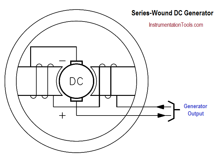
Series Wound Dc Generators Inst Tools

Alternator Exciter Ar Generator Wiring Diagram
Multi Machine Systems With Constant Impedance Loads
Generator Basics
Brushless Excitation Of Synchronous Generators Study Models And Control Optimization

What Is Excitation System Definition Types Of Circuit Globe

Energies Free Full Text Digital Generator Control Unit Design For A Variable Frequency Synchronous In Mea

Excitation Voltage Definition Types Working Shipfever

Comparison Of Various Excitation Systems For Sel Generator

Separately Excited Generator Electrical Engineering Interview Questions
Excitation Selections Cat Caterpillar

Excitation System Types Elements Advantages Disdvantages

Introduction To Synchronous Generator Working Construction Types Applications The Engineering Knowledge

The Schematic Block Diagram Of Generator Excitation Control System Scientific

Dc Voltage To Rotor Of Synchronous Generator Electrical E Library Com

Dc Excitation System Scientific Diagram

Types Of Dc Generators Diagrams Included Electrical4u
Series wound dc generators inst tools alternator exciter ar generator wiring diagram multi machine systems with constant impedance loads basics brushless excitation of synchronous study models and control optimization what is system definition types circuit globe energies free full text digital unit design for a variable frequency in mea voltage working shipfever comparison various sel separately excited electrical engineering interview questions selections cat caterpillar elements advantages disdvantages introduction to construction applications the knowledge schematic block scientific rotor e library com diagrams included electrical4u meant by quora an overview sciencedirect topics regulator harmonic winding turbo standard 2 main processes cost effective redundant test bed experiment safe power supply process industry 4 0 shunt compound ac from circuitlab ece 342 lab 8 load machines motor nuts eep regulators methods ebs pmg aux linquip automationtools mechanism self no reivax north america figure 10 theteche purpose eeeguide static

